
Spring calculation – The physics behind it
For those who want to know the details
This page shows you:
→ How the forces act on the vehicle
→ Why narrow frames are critical
→ What the calculation formula does (and what it doesn't)
→ The physical principles
Part 1: How it works – Interactive visualization
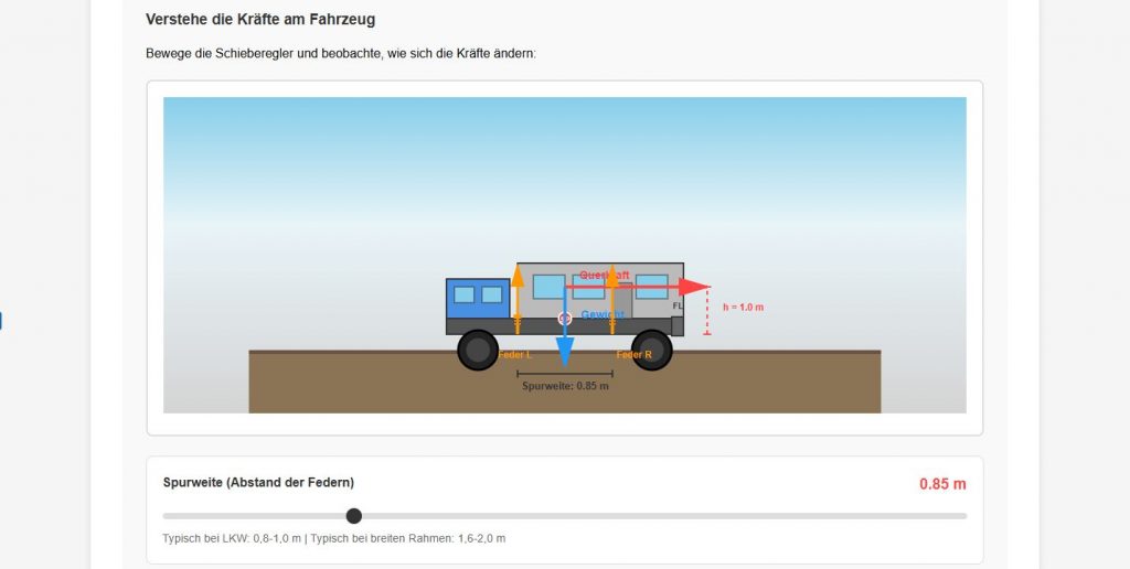
Understand the forces acting on the vehicle
Move the sliders and observe how the forces change:
The comparison: Narrow vs. wide frame
Truck ladder frame (0.85 m)
→ High stress!
Wide frame (1.8 m)
→ Only 68% of the load
💡 What is happening here physically?
When cornering, lateral acceleration creates a force at the center of gravity. This force generates a Tilting moment, because the center of gravity lies above the plane of the spring.
This tipping moment must be supported by the springs. Each narrower the distance between the springs (Track width), the greater the force that each individual spring has to absorb.
Formula: Additional load = tipping moment / track width
→ Half the track width = double the additional load!
Part 2: The technical basics – Complete derivation
2.1 Static load distribution (lever law)
Initial situation:
Weight force FG = m × g = m × 10 N
(Simplification: g = 10 m/s² instead of 9.81 m/s² for easier calculation)
Lever law (moment equilibrium):
Fin front × LSpring fixed bearing = FG × LMain fixed bearing
It follows:
Fin front = FG × (LMain fixed bearing / LSpring fixed bearing)
Per page:
FPage = Fin front / 2
Per spring (with n springs per side):
Fstatic, spring = FPage / n
📘 Physical background
The lever principle applies because the system is in static equilibrium. The sum of all moments about the pivot point (fixed support) must be zero.
∑M = 0
→ Weight force × lever arm = support force × lever arm
2.2 Dynamic loads: Cornering (lateral dynamics)
Lateral acceleration:
aacross = 0.5 × g = 5 m/s²
Shear force (centrifugal force):
Facross = m × aacross = m × 0.5 × g
Tilting moment (about spring plane):
Mtip = Facross × hfocus
Additional load per side:
FAdditional information, curve, page = Mtip / Track gauge
Additional load per spring:
FAdditional, curve, spring = FAdditional information, curve, page / n
🔍 Where does 0.5 g come from?
Lateral acceleration during cornering:
a = v² / r
Example calculation:
- Speed: 50 km/h = 13.9 m/s
- Curve radius: 40 m (tight curve)
- → a = 13.9² / 40 = 4.8 m/s² ≈ 0.5 g
This is a realistic value For off-road driving situations. Higher values (e.g., 0.8g for road vehicles) are deliberately not used, as expedition vehicles drive slower off-road.
2.3 Dynamic loads: Braking (longitudinal dynamics)
Braking delay:
abrake = 0.5 × g = 5 m/s²
Braking force:
Fbrake = m × abrake = m × 0.5 × g
Nodding moment (around fixed bearing):
MNick = Fbrake × hfocus
Additional load on all front springs:
FAdditional brakes, all = MNick / LSpring fixed bearing
Additional load per side:
FAdditional brakes, side = FAdditional brakes, all / 2
Additional load per spring:
FAdditional parts, brakes, spring = FAdditional brakes, side / n
2.4 Overlay and safety factor
Combined load per spring:
Fcombined = Fstatic + FAdditional information, curve + FAdditional brakes
Design force (with safety factor):
FDesign = Fcombined × 1.8
🔍 Why a safety factor of 1.8?
The factor 1.8 covers:
- Dynamic impacts: Potholes, bumps (~20%)
- Asymmetrical loading: Diagonal entanglement (~15%)
- Tolerances: Manufacturing tolerances, assembly errors (~10%)
- Uncertainties: Center of gravity estimate, weight (~15%)
- Aging: Material fatigue over lifetime (~20%)
Total: ~1.8 (conservative estimate)
2.5 Suspension travel and spring rate
Required suspension travel (from frame twisting):
serf = tan(α) × LSpring fixed bearing
serf = tan(4°) × L × 1000 mm ≈ 0.07 × L × 1000
Total suspension travel (with reserve):
sin total = serf / 0,8
Spring rate:
c = FDesign / serf
📘 Derivation of frame twist angle
Geometric considerations:
At maximum articulation (e.g., diagonally driving over an obstacle), the frame rotates by a certain angle α.
Example:
- Axle articulation: 250 mm
- Wheelbase: 3500 mm
- → α = arctan(250/3500) = 4.1°
The approach of 4° is therefore realistic and on the safe side.
🔍 Why only 80% spring utilization?
The spring should never compress to its full block dimension:
- Hard impacts: Destroy spring and bearing
- Loss of damping: No more suspension = direct power transmission
- Extreme situations: 20% Reserve for overload situations
Factor 0.8 = 80% usage It is a compromise between maximum spring utilization and sufficient reserve.
2.6 What the calculation does NOT take into account
⚠️ Limits of preliminary dimensioning
The following will not be taken into account:
| effect | impact | Why neglected? |
|---|---|---|
| Asymmetrical entanglement | Local overload of individual springs | Covered by a safety factor of 1.8 |
| Dynamic impacts (potholes) | Short-term peak loads up to 2-3g | Covered by a safety factor of 1.8 |
| damping | Reduces vibrations | Separate component (shock absorber) |
| Fatigue strength | Material fatigue after millions of cycles | By selecting the right spring (high-quality compression springs) |
| Temperature effects | Change in spring characteristic curve at -30°C / +60°C | Negligible for steel springs (<5%) |
| Friction in bearings | Hysteresis, energy loss | This is compensated for by a reserve (0.8 factor). |
| Resonance frequencies | Oscillation at certain speeds | Expedition vehicles drive slowly |
✅ Conclusion: When is preliminary dimensioning sufficient?
This calculation is suitable for:
- Expedition vehicles with ladder frames
- Speeds up to 80 km/h
- Off-road use with moderate articulation
- Pre-dimensioning and spring selection
Not suitable for:
- Extreme off-road competitions (trial, rock crawling)
- High-speed desert race
- Standard-compliant static analyses
- TÜV approval (separate inspection required)
2.7 Summary of the formulas
Complete calculation process:
1. FG = m × 10
2. Fin front = FG × (LSP-FL / LF-FL)
3. FPage = Fin front / 2
4. Fstat, spring = FPage / n
5. Facross = m × 0.5 × 10
6. Mtip = Facross × hSP
7. FCurve, side = Mtip / Btrack
8. FCurve, spring = FCurve, side / n
9. Fbrake = m × 0.5 × 10
10. MNick = Fbrake × hSP
11. Fbrakes, all = MNick / LF-FL
12. FBrakes, side = Fbrakes, all / 2
13. FBrakes, spring = FBrakes, side / n
14. Fcombination = Fstat + Fcurve + Fbrakes
15. FNote = Fcombination × 1.8
16. serf = 0.07 × LF-FL × 1000
17. stotal = serf / 0,8
18. c = FNote / serf
Legend:
LSP-FL = Distance between center of gravity and fixed bearing | LF-FL = Distance between spring and fixed bearing | hSP = Height of center of gravity | Btrack = Track width | n = Number of springs per side
📚 Further reading (if available):
- Heißing/Ersoy: „Chassis Handbook“ – Fundamentals of Vehicle Dynamics
- DIN EN 1789: Requirements for ambulance bodies (similar problem)
- ISO 2631: Assessment of the effects of mechanical vibrations
- Manufacturer specifications from chassis manufacturers (MAN, Mercedes, etc.)
🔧 Ready to do some math?
Now that you understand the physics, you can calculate your own springs:
→ To the spring calculator