Determine measured values on the vehicle
Instructions for determining the input values for the spring calculation
Why are accurate measurements important?
The accuracy of the spring calculation depends directly on the quality of the input values. Small deviations in the center of gravity or cabin weight have a proportional effect on the calculated spring forces. Even the most accurate calculation is worthless if the input values are off by 20 percent.
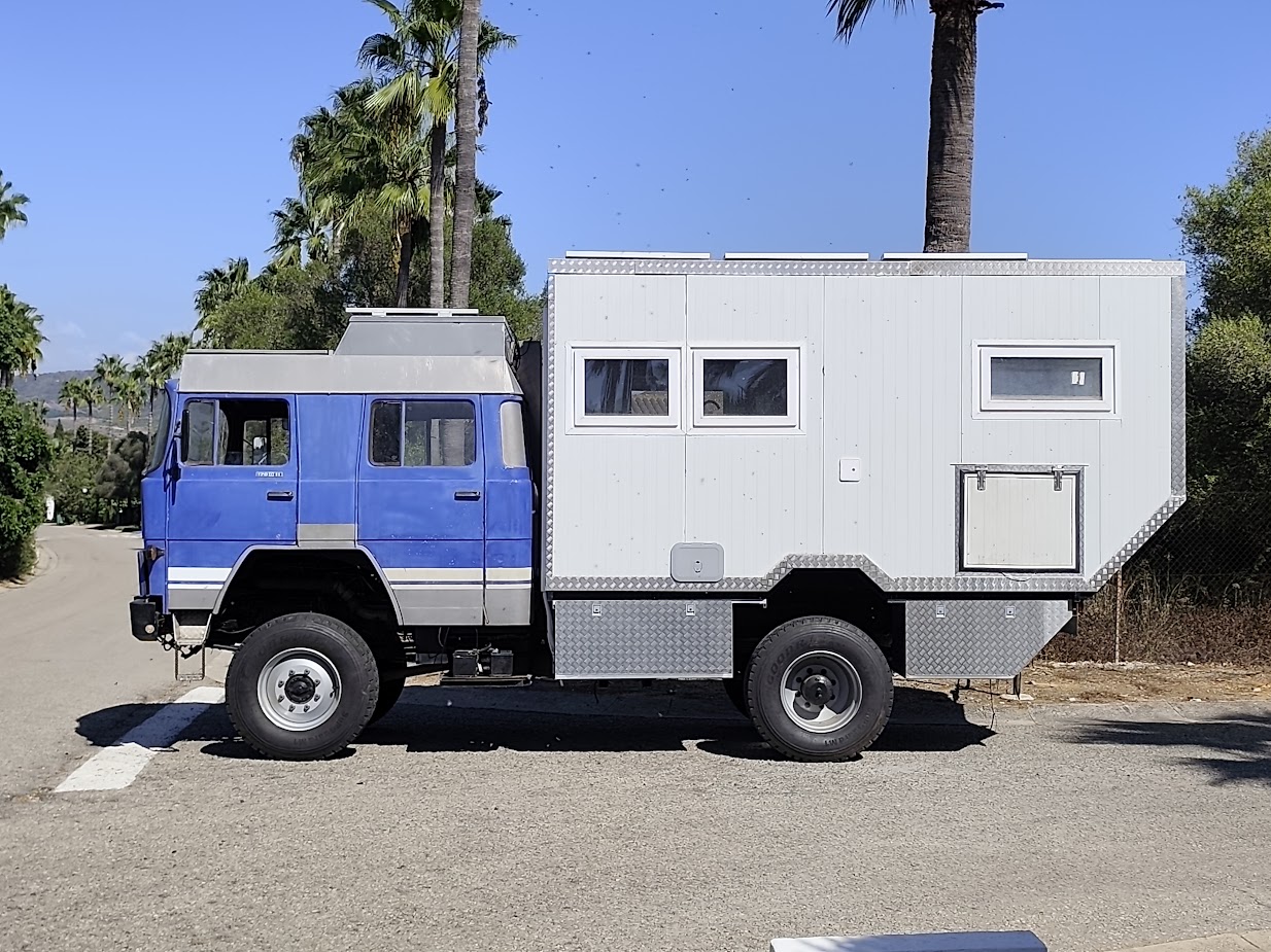
Tip: Click on the numbered points in the image or on the maps below to see details of the individual measurements.
1 Distance fixed bearing to front spring
This is how it is measured:
- Mark the position of the rear fixed bearing (usually at the end of the cabin)
- Locate the position of the front spring on the vehicle frame
- Measure the distance lengthwise with a tape measure or folding rule
- From the center of the fixed bearing to the center of the spring bearing
💡 Typical values
For most expedition vehicles, this value is between 2.5 and 3.5 m.
2 Distance center of gravity to fixed bearing
This is how it is appreciated:
- View cabin floor space
- Use the geometric center as a first point of reference
- Consider heavy components (batteries, water tanks, furniture)
- Shift the center of gravity towards heavy fixtures
- Measure the distance from the rear fixed bearing to the estimated center of gravity
💡 Rule of thumb
With even weight distribution, the center of gravity is often 50-60% of the distance between the fixed bearing and the springs. For the pre-dimensioning of the front springs, use 60% - this is on the safe side.
📋 Example El Bicho (Magirus Deutz 170 D11)
Distance fixed bearing to spring: 2.6 m
Estimated center of gravity: 1.5 m (= 58% of the distance)
Track width at the main frame: 0.85 m
3 Height center of gravity above spring level
This is how it is appreciated:
- With evenly mounted cabin: approx. half cabin height
- Heavy installations below (batteries, tanks): center of gravity drops
- Heavy roof loads, solar panels: center of gravity increases
- Measure from top edge of frame (spring level) to estimated height
💡 Typical values
For an expedition cabin with a height of 2.4 m: center of gravity at about 1.0 to 1.3 m above the spring level. Setting it higher is conservative and on the safe side.
4 Track gauge
This is how it is measured:
- Locate the position of the left spring on the main frame
- Locate the position of the right-hand spring on the main frame
- Measure the distance in the transverse direction (across the direction of travel)
- From center left spring to center right spring
- For truck ladder frames: Springs usually lie directly on the narrow frame (0.8-1.0 m)
💡 Typical values
On truck ladder frames, the track width of the springs is usually between 0.8 and 1.0 m (distance on the narrow main frame). DO NOT confuse with the wheel track width!
⚠️ Critical value!
The track width has an enormous influence on the spring calculation. The narrower the frame, the higher the cornering loads. At 0.85 m instead of 1.7 m, the required spring rate doubles! Be sure to measure correctly.
5 Cabin weight
Method 1 - Weighing (accurately):
- Weigh the vehicle on the vehicle scales BEFORE installing the cab
- Weigh the vehicle again AFTER cab installation
- Difference = cabin weight (incl. subframe, attachments)
Method 2 - Estimating:
- Sandwich panels: 8-12 kg/m² wall area
- Furniture and fittings: 300-500 kg
- Water tanks: 1 kg per liter capacity
- Permanently mounted attachments: Rear carrier, ladder, spare wheel
- IMPORTANT: Round up generously, small parts are often underestimated
⚠️ Important
The cabin weight is the most critical value. If you are unsure, it is better to use 10-15% more - this is on the safe side.
6 Positions of the springs (case B only)
This is how it is measured:
- Mark the position of each spring on the vehicle frame
- Measure the distance from the rear fixed bearing to the center of each spring
- Measure in the longitudinal direction of the vehicle
- Note all distances (from back to front)
📋 Example with 2 springs
Spring 1 (front): 2.6 m from the fixed bearing
Spring 2 (rear): 2.0 m from the fixed bearing
🔧 Calculate the springs now
Have you determined all the measured values? Then let's continue:
→ To the spring calculator for expedition vehicles
🔧 Tool checklist
- Measuring tape or folding rule (at least 5 m)
- Spirit level (for horizontal measurements)
- Marker pen or chalk
- Notepad for measured values
- Optional: laser rangefinder for precise measurements
